In order for the modulator to function, there has to be a non-linearity in the transistor action. Without more details, my guess is that this depends on the variation of HFE with emitter current, that is, as emitter current varies due to the audio input, the HFE changes, which changes the RF gain of the amplifier, which is modulation.
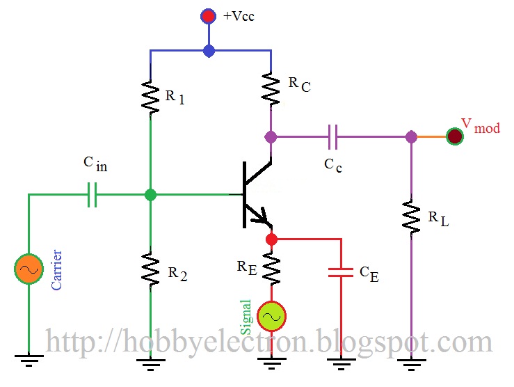
This is an H biased mixer. The carrier input into the base is modulated by the signal on the emitter.
The output is Ac coupled ( V Mod)
What Bill said. Note that the emitter capacitor looks like a low impedance at the carrier frequency (gives high gain), but lets the modulating frequency through the emitter to vary the gain. Crude, and fairly high distortion, but it works.
The gain of the transistor stage at the carrier frequency is gm*Ic*Rc where Ic is the DC (or low frequency) current through the collector. This means that varying the modulation signal will modulate Vout.
http://2.bp.blogspot.com/-Pu-_9pwes-M/Tlu7PkRoLfI/AAAAAAAAAKw/DC6gLIK91C8/s1600/new+fan.jpg
I need a pretty dumbed down explanation if possible. I have to build this circuit but I'm not really sure what each part does. Any help is appreciated!